This website is kept for archival purposes only and is no longer updated.
TESS CAMERAS AND SUN SHADE | ||
 |
 |
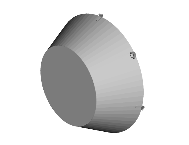 |
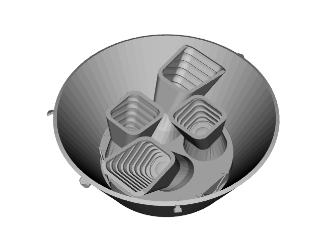
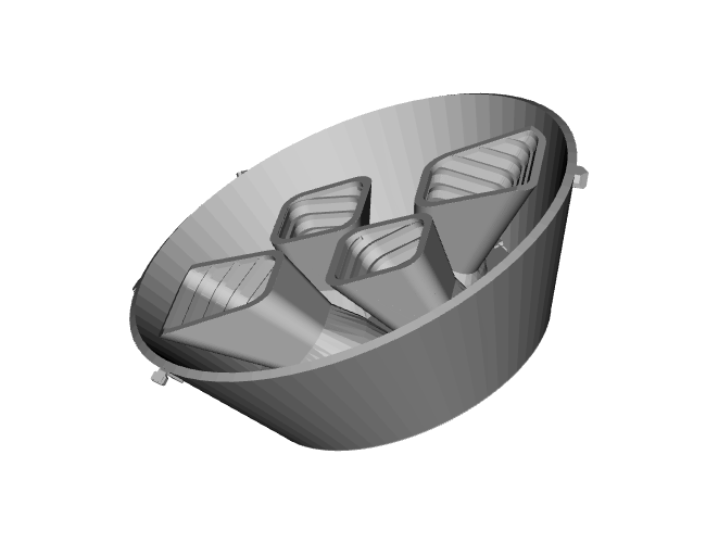
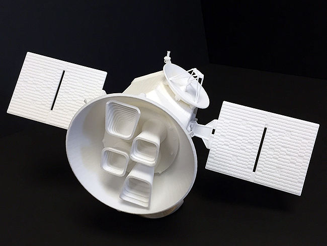
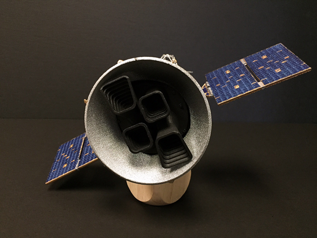
| The TESS instrument is comprised of four identical cameras. Each camera has seven lenses, a package of detectors and electronics to detect transits of exoplanets around distant stars. The cameras each have a lens hood to help prevent stray light from other sources from entering lenses and distorting the light from distant stars that TESS will focus on. The four cameras are placed on a camera plate. The camera plate is enclosed by a sun shade to further protect the cameras from stay light. To learn more about the instrument visit: https://tess.gsfc.nasa.gov/instrument.html |
||
TESS SPACECRAFT |
||
 |
 |
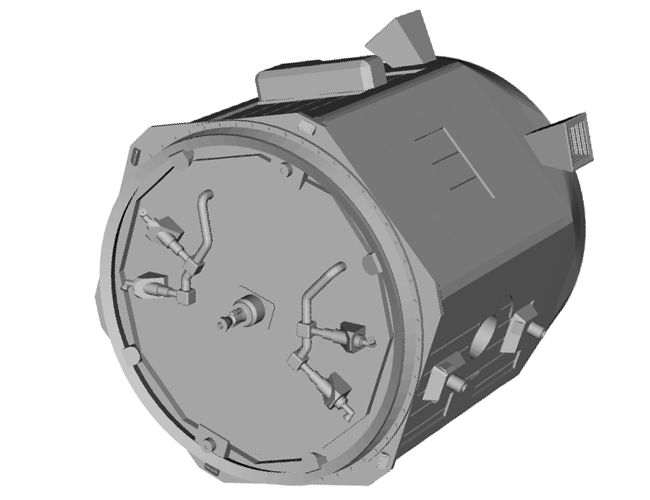 |
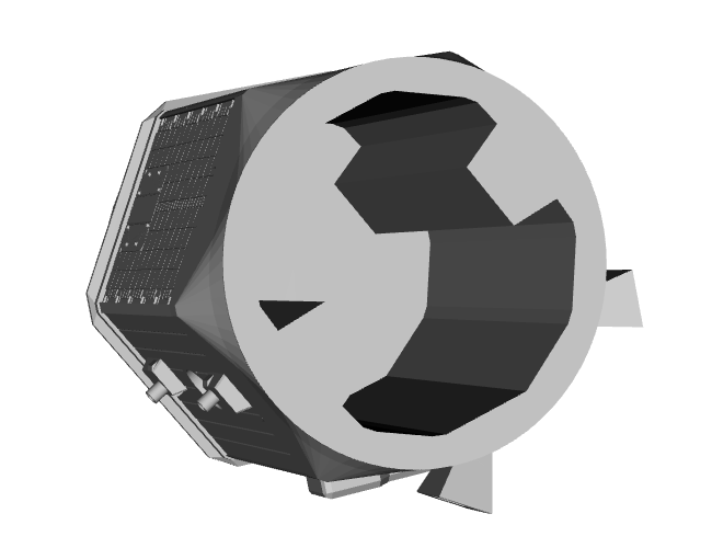
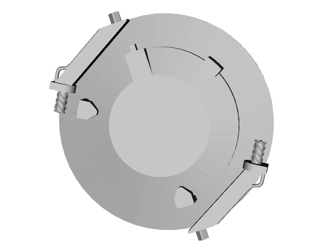
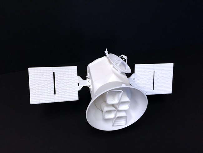
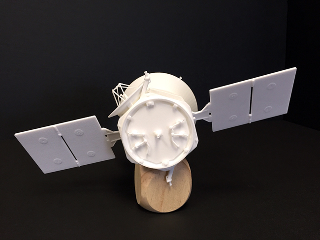
The spacecraft includes the structure and components to support the TESS science instrument. Within the spacecraft, batteries, propulsion (fuel, and thrusters), reaction wheels computers for commanding the spacecraft and transmitting data all allow the TESS science instrument to complete the mission for finding ne exoplanets. To learn more about the spacecraft visit: https://tess.gsfc.nasa.gov/spacecraft.html
| ||
TESS ANTENNAS | ||
 |
 |
 |
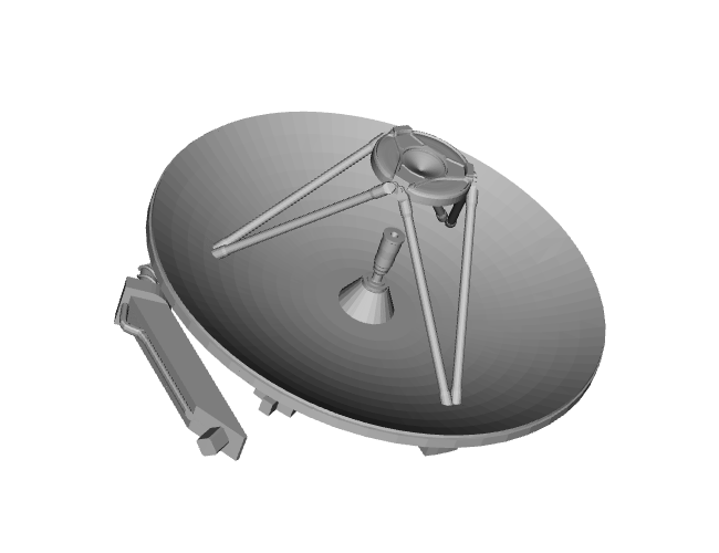
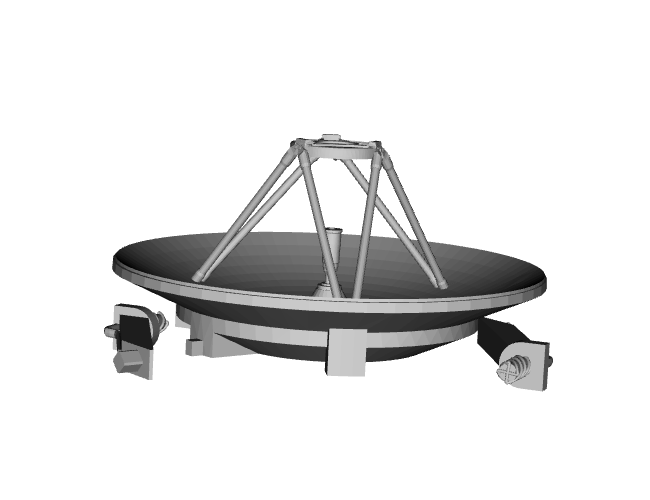
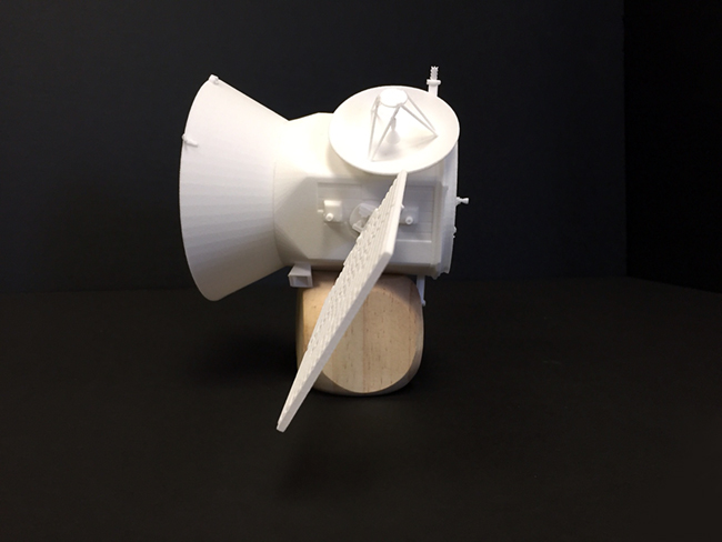
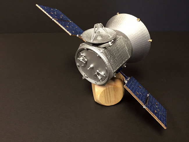
The antennas on TESS allow for the transmission of commands to the spacecraft and instrument. Also, the antennas allow the TESS spacecraft to transmit data collected by the TESS instrument back to Earth for analysis. The large circular dish is the High Gain Antenna; the two smaller antennas are S-Band antennas.
| ||
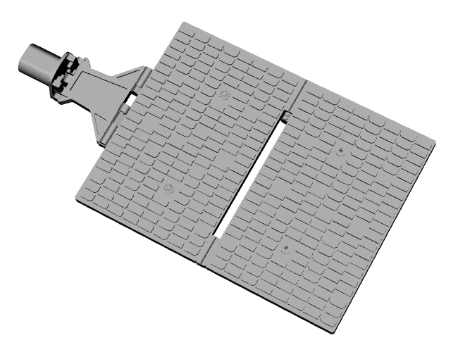
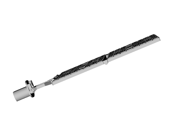
TESS SOLAR ARRAYS | ||
 |
 |
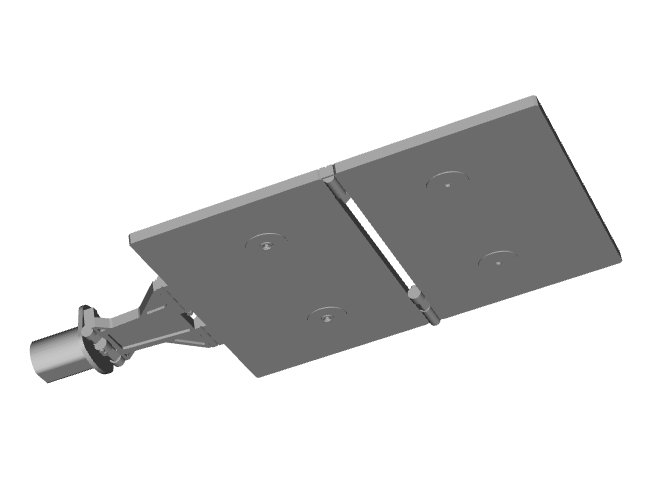 |
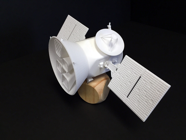
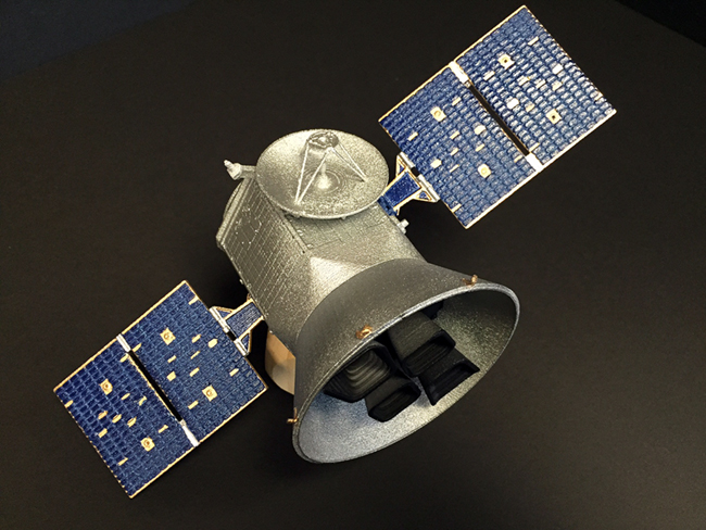
Spacecraft operating in the inner Solar System usually rely on the use of solar panels to derive electricity from sunlight. Solar panels on spacecraft supply power for the instrument and spacecraft systems. Solar panels need to have a lot of surface area that can be pointed towards the Sun as the spacecraft moves. More exposed surface area means more electricity can be converted from light energy from the Sun.
| ||
ASSEMBLY INSTRUCTIONS |
|
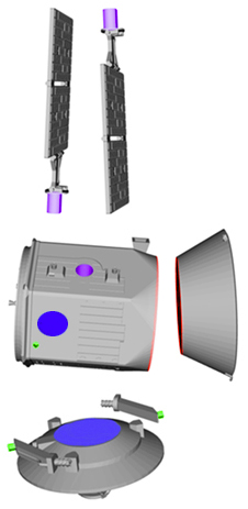 |
After downloading all of the .stl files [Antennas.stl, Body.stl, Cone.stl, and SolarPanel.stl] separately or all at once as a zip file [TESS_3D_Model_Files.zip] you will need to print them on your 3D printer or online at one of the many places that provide 3D printing services. You will need to print one of each file except for the solar arrays. You will need to print two of the arrays (see the image to the left). Note: The Antennas.obj file come out as 3 pieces. All other files are one piece. Once you have all your parts printed, you will need glue to assemble the parts to complete the model. We recommend researching which type of adhesive/glue to use based on the materials that your 3D printer utilizes. The image to the left is color coded to help with putting the parts in the correct place.
|
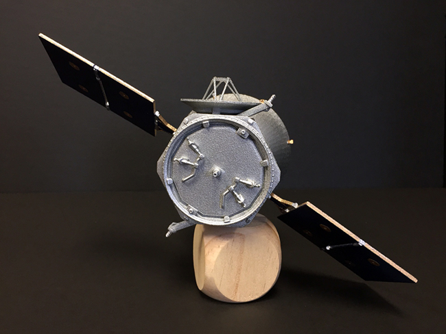
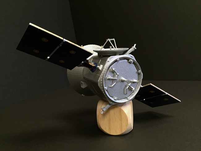
REFERENCE IMAGES |
||
 |
 |
 |
 |
 |
 |
 |
 |
 |
 |
||
| Connect with us | |||
 |
 |
 |
 |