|
This website is kept for archival purposes only and is no longer updated.
Progress
In our original InFOCmS proposal we requested $2600K and promised to fly by the end of the 3 year cycle. We received $1880K and were told to demonstrate the key technologies necessary to build the flight instrument. We have demonstrated the detectors, mirrors, and key pointing system elements required for the flight system and are now ready to build the instrument.
Demonstration Model Telescope
In the previous program of the InFOCmS project, we have developed the supermirror hard X-ray telescopes in three steps in collaboration with NASA/GSFC.
Design of the Demo Model
To utilize the ASTRO-E XRT hardware, the following ASTRO-E telescope parameters were chosen:
|
Focal length
|
|
=
|
|
4.75 m
|
|
Foil diameters
|
|
=
|
|
12 to 40 cm
| |
Incident angles
|
|
=
|
|
0.11o
to 0.36o
|
These parameters provide equivalent incident angles to the flight telescopes. For the demonstration, 0.3o is employed, at which the thinnest multilayers are needed. The multilayer supermirrors of Pt/C are designed to optimize for the energy range from 25 to 40 keV. We have designed the supermirrors with 4 blocks of constant spacing multilayers as:
|
Block #
|
|
|
I
|
|
|
II
|
|
|
III
|
|
|
IV
|
|
N
|
|
|
5
|
|
|
8
|
|
|
13
|
|
|
18
|
|
2d(nm)
|
|
|
4.6 to 5.0
|
|
|
4.0
|
|
|
3.6
|
|
|
3.3
|
Since the fourth block adds only a narrow band of 3 keV with 60% more layers, we decided to use only three-block supermirrors for the demonstration model.
Fabrication of Supermirror Reflectors
The mirror substrate is the Au replica mirror shells developed for ASTRO-E XRT by the Goddard X-ray group. Pt/C multilayers are deposited on 20 of them with the DC magnetron sputtering system at Nagoya University. The uniformity on individual samples and among 20 samples is better than 2% fluctuation in thickness and reflectivity. Measured reflectivity is 20% to 30% for X-rays between 24 and 36 keV (Fig. 1).
Fig. 1. X-ray reflectivity of the supermirror.
X-ray Imaging Experiment
Twenty foils with supermirror coatings are installed in the two stages of the ASTRO-E XRT housing (Fig. 2). The model telescope thus fabricated is placed in the 50 m X-ray (diverging) beam line at GSFC to illuminate it with X-rays up to 50 keV. The focal plane images are obtained with a CCD camera and the CdZnTe strip detector developed by the gamma-ray group at GSFC. The image size is detected as 2.4 arcmin HPD in the energy range from 24 to 36 keV (Fig. 1). This is the first hard X-ray focusing experiment with a supermirror in the world.
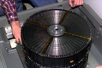
Fig. 2. ASTRO-E mirror.
GSFC Mirror Work
We have investigated a technique we have named "direct replication" — where the complete set of multilayers is deposited onto a glass mandrel and joined to an aluminum foil in a similar manner to surface replication. This technique is useful because the top layers — which dominate the reflectivity of the mirror foil — will adapt the smoothness of the glass mandrel and will not suffer from the accumulation of roughness errors in the layers beneath. Fig. 3 shows two reflectivity curves of a sample foil using this direct replication method measured 6 months apart. The consistency of these two measurements demonstrates that direct replication is a very stable way of depositing multi-layers onto foils.
Fig. 3. Reflectivity of Pt/C mutilayer measured at 6 month interval shows stability.
The DC magnetron sputtering system at GSFC is capable of consistently depositing very uniform layers either onto glass mandrels or foils. The sputtering system has two possible configurations–one with the targets at the edge of the rotating table pointing in to sputter onto glass mandrels and the other with the targets at the center of the rotating table pointing out to sputter onto foils. This unique configuration gives us a great amount of flexibility in how we apply multi-layers to foils and the unique capability to mass produce multi-layered foils via direct replication.
Detector Work
We received a run of 55 spare readout mode ASICs from a MITEL run. They were tested for functionality and quality using our probe station. The yield for our ASICs was 65% and 12 indium bump-bonded hybrids have been made. Both CZT and CdTe material were used with thicknesses of 2, 1, and 0.5 mm.
Shield System Work
The first CsI(Tl) crystal was installed in our housing by Bicron (Fig. 4). The energy resolution for the entire shield assembly is 9% to 15% at 661 keV. The signal processing chain of electronics for the shield has been designed, built, and tested. We achieved a very low effective operating threshold of 15 keV, which from our GRIS shield experience is far below the required threshold to achieve the lowest attainable background contribution due to the shield subsystem. The PMTs have been tested for linearity, noise, and recovery to saturating events — all are very acceptable.
Fig. 4. CsI shield housing and crystal.
Truss Work
All the carbon-fiber tubes have been fabricated (tubes made, end-fittings epoxied on, and pull-tested) for a complete 8-m flight truss (plus about 15% spares). Half of the truss (4 m) has been assembled to allow static and dynamic load testing (see Fig. 5). Going from 0-load to full load (representing a range of elevation angles from 90o to 0o, the maximum bending moment is 2 mm (i.e., 6 pixels), which is well within our detector active area and equal to the NASTRAN simulation results.
Fig. 5. InFOCmS half truss static loading test.
Floating-Ball Work
The flight cup-n-ball have been fabricated and connected to a test pump and test mass to simulate the 2000 lbs of the gondola (Fig. 6). Tests show that the flow pattern of the hydraulic fluid is symmetric between the cup and ball and that the asymmetric flow-induced torques are less than 5 g-m. The friction of the assembly is less than 6 g-m, which is well below the other disturbing torques in the system and less than the quantization in the momentum wheels.
Fig. 6. Floating-ball decoupler test.
GSE Work
The ground support equipment (GSE) computers are in hand and the software to control the ground-based development & calibration activities plus InFOCmS instrument flight controllers have been bought. Software has been developed and is currently being used for the development stage testing and calibration of the standalone detector subsystems. The software for the flight operations and control of the InFOCmS instrument has already been written and is being used during the integration of the instrument. This amounts to 26,000 lines of C-language code, of which about half was carried over from our previous GRIS instrument effort.
Test Flight Work
Prior to the full-up InFOCmS gondola and detectors, we are building a smaller "test" gondola for measuring the basic CZT detector operation characteristics and the detector background at balloon altitudes . The gondola structure is built. It contains the actual InFOCmS flight pressure vessel, the flight Instrument and Detector mCs, the power control sub-system, and the interface to the NSBF CIP package. All the flight software for these two mCs is written.
|