|
This website is kept for archival purposes only and is no longer updated.
Detector
We have demonstrated that the necessary performance for the focal plane of InFOCmS can be achieved with the CZT hybrids developed by GSFC and the University of Arizona. Spatial resolution, energy resolution, and variations in CZT material properties are all strongly coupled. Careful selection of material and an optimized event analysis algorithm is required to extract the most from these detectors. We have a measured resolution for the best material of 2.3 keV in a single pixel (collimated beam of 109Cd in the center of a pixel with 100 Ás integration; see Fig. 1). We have shown that by cooling to < -25°C, we can achieve the same leakage current noise levels for integrations of 1 ms that give > 85% livetime. If the charge spreading were negligible, we could achieve nearly the same resolution for flood illumination of the whole detector (see material selection section). For detector material of a typical quality that we used in our current hybrids, this single pixel resolution is degraded to 3.4 keV for flood illumination data analyzed with an optimum algorithm. The 380-mm pixels are quite sufficient to resolve the PSF of the mirror, but subpixel position determinations may be required near the pixel edge to get the best energy resolution.
Fig. 1. Energy spectrum in a single pixel.
Depth estimation is important for InFOCmS because the focused photons interact near the front surface but the background is produced uniformly throughout the detector (Parsons et al. 1999). Fig. 2 shows an image of a narrow collimated beam of gamma rays incident at 45 degrees and estimated the 3-d coordinates of each interaction. Possessing an accurate model of the detector allows us to calculate the depth of interaction directly from the pixel signals, information that is unobtainable without the ability to accurately simulate the full effects of charge trapping and signal induction. When a gamma ray generates a charge cloud, the holes are trapped quickly and fail to reach the top electrode during the ~1-ms integration time, while the electrons all traverse the detector without trapping. These trapped holes attract a negative charge on the pixel electrodes that gets stronger the closer the holes are to the pixel electrodes. Our maximum-likelihood estimation procedure includes these negative signals, so it produces accurate estimates of all 3 spatial coordinates and energy. The comparison of the derived energy with the top side contact pulse height is a direct and independent measure of the hole collection deficit and depth of interaction. We will be developing an analysis procedure that combines these techniques to optimize the depth determination.
Fig. 2. Interaction depth determination for a collimated beam at 45° slant.
The uniformity that can be obtained from our hybrids is illustrated by a shadowgram of a key obtained with a CdTe detector. We have chosen this material because it has very good uniformity. This illustrates how good the uniformity should be with improved material and this material is still under serious consideration for our flight system. It has very good mechanical properties. (The shadowgram was made with a 0.5-mm thick CdTe detector.) This material also has very good electron and hole mobility. Unfortunately, its lower resistivity requires lower operating temperatures which in turn require higher bias voltage. This material also suffers from polarization effects that require periodic cycling of the bias voltage.
Fig. 3. Shadowgram of a key on a CdTe detector made with an 241Am source.
Material Selection
The Materials Engineering Branch at GSFC has developed two complementing nondestructive techniques for characterizing CZT. The first technique, infrared (IR) transmission imaging, allows for rapid visualization of bulk defects such as cracks, telluride decorated grain and twin boundaries, voids and dispersed telluride inclusions. The second technique, X-ray spectral mapping, provides a map of the material response when it is configured like an actual detector. These two techniques have been used to develop a correlation between bulk material defects and detector performance.
Based on the correlation, we have implemented a program where wafer slices of CZT are screened using the IR imaging to identify areas that have the best potential for producing uniform detectors. The specimens that are mined out of the wafer slices are then fully characterized using the X-ray spectral mapping technique. This approach has yielded numerous CZT specimens with excellent uniformity. The images below show X-ray spectral maps of a typical specimen. The maps were acquired using a 250 micrometer collimator and 250 micrometer step size. The plots correspond to peak-channel location. The 26.9 by 26.9 by 2 mm thick specimen was mapped as four quadrants in order to keep leakage current levels manageable.
Fig. 4. High-resolution X-ray scan of CZT procured by wafer scale selection. The grey scale corresponds to the photopeak channel.
The Readout ASIC and Hybrids
The InFOCmS readout ASIC is a large pixel device, 26.8 X 28.6 cm with a 64 X 64 pixel array on 380-mm pitch. The ASIC is modeled on integrating IR focal planes and was designed by Augustine Engineering. We have chosen this design because it can be easily be implemented in smaller pixel sizes down to < 50 Ám to accommodate higher resolution mirrors. The circuit stores two integrations of signal on separate capacitors in each pixel. A sparse readout circuit rapidly compares the two integrations to determine which pixels contain the photon hit. The appropriate pixels are readout under random access control. The ASIC is connected to the pixel contact on the CZT detector by indium bump bonding. This is a standard process used for IR focal planes and is capable of connecting pitches as fine as 12 um. Each pixel on the detector is connected to an input on the ASIC by an indium bump bond. This is a standard IR focal-plane assembly technique and is compatible with the full temperature range we might use with CZT or CdTe (-40 to 20°C).
Detector Electronics
The detector electronics chain is comprised of three electronic assemblies: daughter board, driver board and hit processor controller board. The daughter board is a flexible printed circuit which provides the mount for the detector hybrid and wraps around the cold finger cube. The driver board provides local control logic, all the analog electronics, and the video ADC. The hit processor is an FPGA based system that resides in the detector mC. It controls the sparse readout and all other specialized functions of the focal-plane system. Four hit processors can be supported in the detector mC.
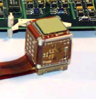
Fig. 5. Focal-plane detector assembly.
Shield
The main function of the shield system is to provide an anticoincidence for background rejection in the CZT detectors. The shield system consists of a CsI(Tl) scintillator in a housing with 12 PMTs (Fig. 6). The minimum thickness is 1 inch of CsI(Tl). The housing is designed to minimize the amount of passive material inside the shield (all the inner walls are 20 mils of aluminum). The shield driver card provides all the signal conditioning, thresholding, and housekeeping circuits. The shield card interfaces to the detector mC through a serial interface to the hit processor card.
The anticoincidence is made between the shield and a signal derived from the top contact of the CZT detector. The hit processor only reads out events that have one unvetoed event during an integration. In normal operation, all other integrations are reset immediately with no readout. Deadtime is minimal because the background rate is very low.
Micro-Computer Architecture
To handle all the diverse activities of InFOCmS, there are five on-board computers. They are the central instrument mC and the detector, pointing and two star camera mCs. They are linked through a local area network using TCP/IP. The real-time, multi-tasking QNX operating system is used for the embedded flight software.
Attitude Control System
The pointing system on InFOCmS is configured as a three-axis stabilized attitude control system using star trackers and gyros as primary attitude sensors and reaction wheels as primary torque actuators to accomplish arcsec-level inertial pointing. Magnetometers, inclinometers, and sun sensors are also included for coarse pointing and to initialize fine pointing acquisition. To maintain the reaction wheels within their linear limits, fine balance weights will be adjusted slowly to dump disturbance torque momentum in the horizontal plane while magnetic coils are used to unload the vertical component. The ACS algorithm runs at 10 Hz and uses PID plus Kalman filtering techniques to achieve the arcsec pointing stability requirement.
Fig. 6. CsI shield housing and crystal.
Gondola Structure
The major elements of the gondola are the 8-meter-long truss, the "doghouse" containing the most of the electronics and control systems, and the mid-section between the truss and doghouse. The mid-section has the floating-ball and cup assembly. The truss supports the mirror assembly at the front end and the detector assembly in a pressure vessel at the back end. The truss is an open-frame structure made with 9-cm diameter carbon-fiber tubes in a standard triangulated structure, which provides the requisite stability between the mirror and detector ends and a minimum weight. The floating ball and cup is the 3-axis pivot point on which the gondola structure maneuvers to slew to and to tract the desired target.
Management Plan
InFOCmS is an ambitious balloon payload that requires a large and capable team to execute successfully. We have tried to make maximum use of existing facilities and capabilities and the synergy with programs both funded by NASA and other sources to put together a package that can bring this new technology to an operational state in the minimum time. The mirror team is a strong existing collaboration between the GSFC X-ray group and Nagoya University. This team has a long history of close cooperation on major projects (ASCA, ASTRO-E) and plans for ASTRO-G that include multilayer mirrors. The Nagoya group is providing substantial support for this instrument.
Our detector team is a close collaboration between the medical imaging group at the University of Arizona lead by Dr. H. Bradford Barber and the GSFC gamma-ray group and the Detector Development Lab. We are jointly developing the pixel readout detector based on the same design by Augustine Engineering. Carl Stahle of the DDL is providing support of unique detector fabrication technology to this joint effort. The DDL and gamma-ray group work closely as leaders in the development of CZT as a space-flight detector technology for hard X-rays. The University of Arizona group is funded by NIH to make ~100 of these detectors for high-resolution SPECT animal imagers. We will be jointly developing techniques for hybridization, screening and testing of detector material, readout electronics, and event analysis algorithms including depth determination. All of these areas are crucial to both projects and can be accomplished with similar hardware and software.
Our gondola team is the gamma-ray group from GSFC and Marvin Leventhal (University of Maryland) who has a long history in ballooning and has had a close relationship with our group since we collaborated on the GRIS instrument. We have been and will continue to receive substantial support from the engineering directorates at GSFC.
The breakdown of the specialized effort of individual CoI's are given on the personnel summary page. The GSFC gamma-ray group and the DDL has responsibility for development of the focal-plane detectors. They will coordinate their activities with the development work at the University of Arizona and in the areas of ASIC development and hybrid assemble. We expect this to be particularly useful to InFOCmS because of the large number of hybrids that will be fabricated in the Arizona program. They are developing procedures to lower costs and recycle detector material. We also expect a continued close collaboration with an InFOCmS-funded grad student at Arizona working on the event analysis software.
The responsibility for the mirror will be a collaboration between the GSFC X-ray group and Nagoya. The mirror housing and the foil replication will be performed at GSFC. The Nagoya group will provide at least one person at GSFC to support this work. Multilayering will be performed in facilities at both institutions.
9. Schedule
Test Flight - 8/99
First Mirror Ready - 11/99
Flight Detectors (1-4) - 11/99
Pointing System Tests - 1/00
First Flight - 5/00
Second Flight - 5/01
Second Mirror - 11/01
Mirrors 3&4 - 11/02
Australia Flight - 10/02
To see the literature references click here.
|