|
 (Shuttle Mission: STS-61)
Shuttle: Endeavour
Date: December 2-13, 1993
Servicing Mission 1, launched in December 1993, was the first opportunity
to conduct planned maintenance on the telescope. In addition, new
instruments were installed and the optics of the flaw in Hubble's
primary mirror was corrected.
COSTAR
After Hubble's deployment in 1990, scientist realized that the telescope's
primary mirror had a flaw called spherical aberration. The outer edge
of the mirror was ground too flat by a depth of 2.2 microns (roughly
equal to one-fiftieth the thickness of a human hair). This aberration
resulted in images that were fuzzy because some of the light from
the objects being studied was being scattered.
COSTAR
(the Corrective Optics Space Telescope Axial Replacement) was developed
as an effective means of countering the effects of the flawed shape
of the mirror. COSTAR was a telephone booth-sized instrument which
placed 5 pairs of corrective mirrors, some as small as a nickel coin,
in front of the Faint Object Camera, the Faint Object Spectrograph
and the Goddard High Resolution Spectrograph.
COSTAR Animation
(RealPlayer)

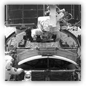
WFPC2 in the enclosure
|
Wide Field Planetary
Camera 2 (WFPC2)
WFPC2 significantly improved ultraviolet performance
over WFPC1, the original instrument. In addition to having more
advanced detectors and more stringent contamination control,
it also incorporated built-in corrective optics.
|

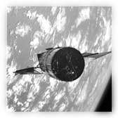
Image of solar arrays
prior to capture
|
In addition, SM1 included
the installation and replacement of other components including:
Solar Arrays
Solar Array Drive Electronics (SADE)
Magnetometers
Coprocessors for the flight computer
Two Rate Sensor Units
Two Gyroscope Electronic Control Units
GHRS Redundancy Kit
|
|