 |
 |
ARCADE External Calibrator
ARCADE achieves its precision by comparing the sky to
an onboard calibrator, which serves as a blackbody
at a known temperature to compare to the unknown sky.
To be effective, the calibrator must meet the following criteria:
It must be black (emissivity > 0.999 or reflectivity < 0.001)
across ARCADE's full five octaves of frequency coverage
(3 GHz to 90 GHz, or wavelength 10 cm to 3 mm).
It must be nearly isothermal so the emitted power
can be tracked by thermometers imbedded within the absorber.
It must be controlled to remain at a fixed temperature
near the 2.7 K sky temperature,
despite sitting at the top of an open bucket dewar.
It must be compact enough to fit at the top of the dewar
without sticking up out of the protective "bubble" of
cold helium gas, and must be
light enough to fly as a balloon payload.
Most of these requirements conflict with each other. Achieving
high emissivity generally requires absorbing elements many wavelengths
long, which for the longest ARCADE wavelength of 10 cm would imply
a height of over half a meter. A calibrator of this size would certainly
stick out of the cold helium "bubble" over the dewar, leading to runaway
warming from the outside world. Microwave absorbers are typically poor
conductors of heat. Minimizing thermal gradients across the calibrator
requires metal surfaces, which are highly reflective.
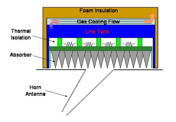
We achieve the goals of high emissivity in an isothermal, compact calibrator
using composite absorbing structures in a tiled design.
The figure above shows a schematic of the on-board calibrator.
A set of 295 composite cones in a hexagonal close-packed array
form the absorbing surface. The absorbing cones are mounted on a
thermal diffusion plate and are weakly coupled to a tank containing
superfluid liquid helium. The helium tank surrounds the calibrator
on the sides and top to intercept heat leaks from the outside world.
Boiloff gas from the tank is vented around the outside of the tank
to further reduce the heat leak through the enthalpy of the cold gas.
Layers of foam insulation and aluminized mylar provide additional
thermal protection.
|
|
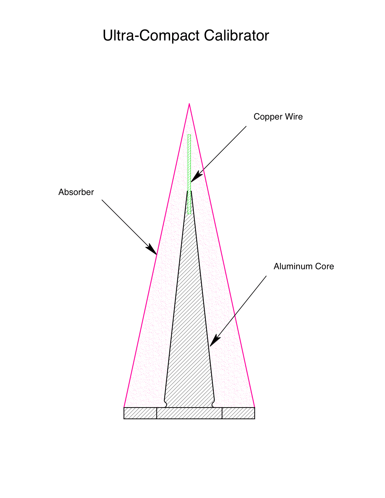
Schematic of a single absorbing cone
|
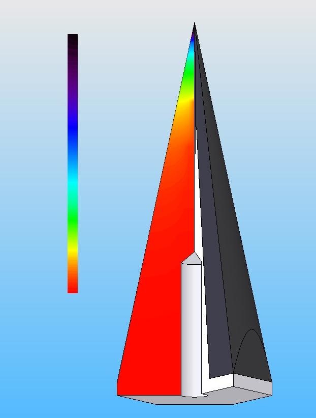
Thermal model showing gradient from
the back plate to the colder tip region.
|
The forest of cones provides high microwave emissivity
in a compact footprint
while minimizing thermal gradients in the absorber.
Each cone is 88 mm tall
and consists of an aluminum core with a
7 mm absorbing "skin"
made from stainless steel powder
suspended in a commercially available epoxy
(Stycast 2850-FT).
A copper wire extends from the aluminum core
into the absorber tip region.
Together, the aluminum and copper
provide a path withb high thermal conductivity
to reduce gradients within each cone.
With the calibrator temperature
held 1.2 K above the aperture temperature,
95% of the absorber volume lies within 5 mK of the target base temperature.
This is the expected thermal performance for the July 2006 flight.
Later flights will control the aperture temperature
to more closely match the calibrator temperature.
With a reduced gradient driving heat through the absorber,
flights of a 3rd generation instrument should reduce
gradients below 0.5 mK within the calibrator.
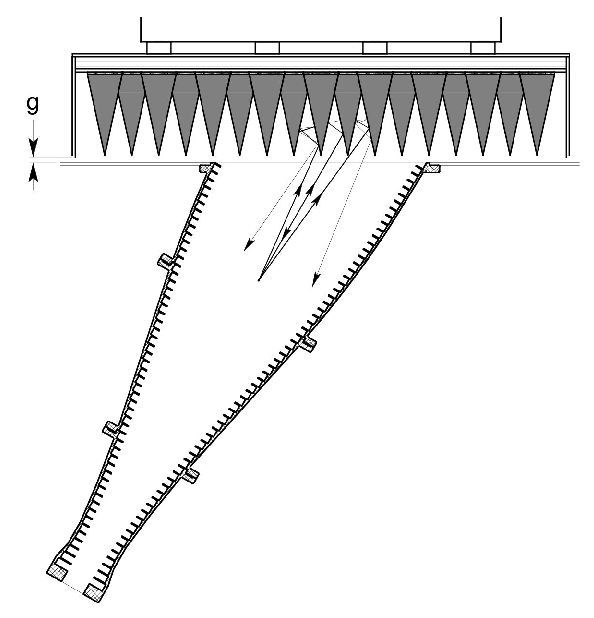
The figure above shows the calibrator in flight configuration.
Each antenna views the calibrator at an angle 30 degrees
from normal incidence.
Radiation from the antenna has multiple reflections
within the forest of cones,
increasing the effective emissivity of the calibrator.
Leakage through the gap (labeled "g")
between the calibrator and the antenna aperture
is small (measured to be less than -50 dB).
The table blow shows the measured power reflection coefficient
for the calibrator and antenna in flight configuration.
Despite a height less than 0.8 wavelength,
the calibrator is black (emissivity greater than 0.9999)
over more than 5 octaves in frequency.
ARCADE Calibrator Power Reflection Coefficient
| Waveguide |
Channel |
Reflected Power |
| Designation |
(GHz) |
(dB) |
| WR284 |
3.4 |
-42 |
| WR187 |
5.6 |
-56 |
| WR112 |
8.3 |
-69 |
| WR90 |
9.8 |
-63 |
| WR28 |
30 |
-56 |
| WR10 |
90 |
-57 |
ARCADE is a double-nulled experiment:
we adjust the temperature of the internal load on each radiometer
to match the sky temperature,
and then allow each antenna to alternately
view either the sky or the blackbody calibrator.
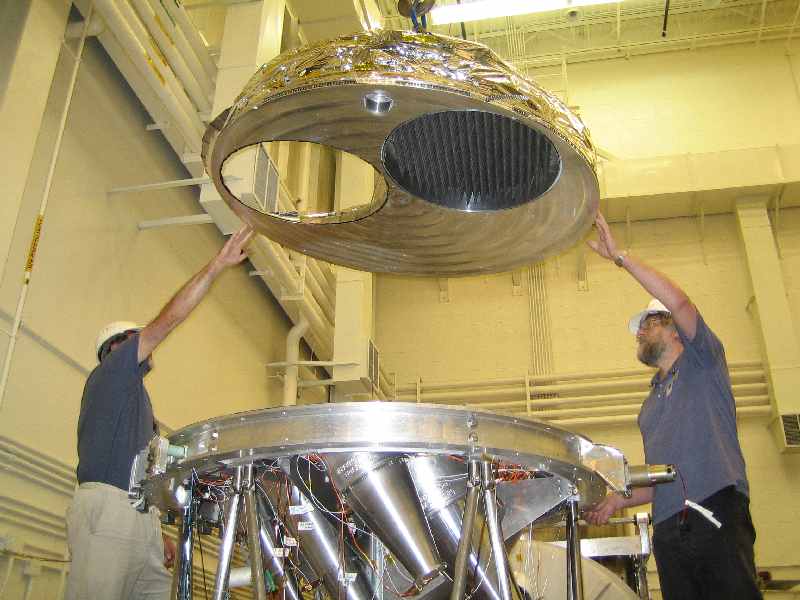
The figure below shows the calibrator being lowered
onto the instrument core.
The calibrator cones are visible through the elliptical opening
in the right of the "lazy susan" support structure.
On the left is the hole allowing the antennas
to view the sky.
Several feed horns are visible at the bottom of the picture.
|
|